
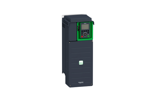
The solution of Schneider inverter fault code
Published:2023-02-23 15:32:20
PHF: ⒈ Frequency converter power supply is not correct or fuse is blown; B. There is momentary defect in some phase. ⒈ Check the power supply connection and fuse; B. Reposition.
USF: ⒈ Supply voltage undervoltage; ⒉ Instantaneous voltage drop; 3. The load resistance is damaged. 1 Check the power supply voltage. 2 Replace the load resistance.
OSF, OHF, OLF, ObF, OPF, LFF, OCF: power supply voltage is too high check the power supply voltage radiator temperature is too high monitor the motor load; Inverter ventilation; Reset after the frequency converter is cooled; Thermal maintenance trip due to excessive overload time. 1 Check the hot maintenance Settings. Monitor the motor load 2 Wait about 7 minutes before restarting the braking too fast or the load is too heavy to extend the deceleration time, if necessary, add the brake resistance output phase check
4 -- 20 mA signal loss of motor connection AI2 port: check the given circuit 1. Too short a slope; 2. Excessive inertia or heavy load; 3. Mechanical slot. 1. View the Settings. 2. Check the motor/frequency converter/load capacity; 3. Check the mechanical condition.
SCF CF: The output side of the converter is short-circuited or grounded. Check the bridge resistance of connecting cable and motor insulation converter. 1. Load relay operation fault; 2. If the load resistance is damaged, check the connector and load resistance in the converter.
SLF O F S F EEF InF: Frequency converter ports are incorrectly connected. Check the connection of the converter interface, motor overheating (PTC sensor), motor ventilation and ambient temperature, check the type of sensor used, detect the fault of connecting the motor load sensor to the converter, check the fault of connecting the sensor to the converter EEPROM storage, block the power supply of the converter and reset it. 1. Internal faults; 2. Interface faults Check the interface of the frequency converter.
EPF SPF AnF: external chain fault. Check the faulty equipment and reset, no speed response, check the speed sensor connection and mechanical coupling. 1. Not following slopes; 2. Reverse the speed to the set point. 1. Check the speed response Settings and wiring; 2. Check whether the Settings for a specific load are appropriate. 3. Check the capacity of motor -- frequency converter, and whether brake resistance is needed.
SOF: 1. unstable; 2. The load is heavy. 1. View Settings and parameters. 2. Add brake resistance; 3. Check the capacity of motor/frequency converter/load.
CnF: Communication fault in the field bus. 1. Check the network connection of the converter; 2. Check the communication faults between the timeout ILF option board and the control board. Check the connection between the option board and the control board.
CFF: The fault that may be caused after replacing the board. 1. Nominal change of power plate; 2. Change the palette type, or install the palette when there is no palette but macro -- the equipment is CUS; 3. Remove the option panel; 4. Can't save inconsistent equipment. 1. Check the hardware equipment of the converter (power or other); 2. Cut off the inverter power supply and reset it; 3. Store the equipment in a file in the display module; 4. Press ENT twice to restore factory Settings (** Press ENT twice, the following information will be displayed: Fact.Set? Restore ENT/ESC to factory defaults? ENT/ESC)
CFI: Inconsistent equipment being fed into frequency converter through serial port. 1. Check the equipment that has been sent; 2. Send an identical device.
-
 202301-05
Siemens F7453 after the treatment measures
1. Cause F7453 occursWhen Epos function is used, a bearing ring encoder will be set. If the numerical feedback of the bearing ring encoder presents problems, F7453 problems will be reported, represent···
-
 202302-14
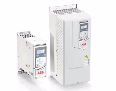
ABB frequency converter maintenance method
The repair method of ABB frequency converter needs to be properly grasped. The frequency converter is composed of various components, among which the performance of some components gradually decreases···
-
 202410-21
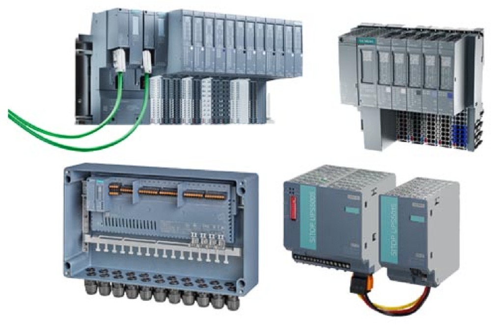
Input and Output Modules: Everything You Need to Know
I/O modules(input/output modules)manage the communication between the CPU and the network,including data transfer,power load management,and machine function control.It enables system integrators to co···
-
 202303-03
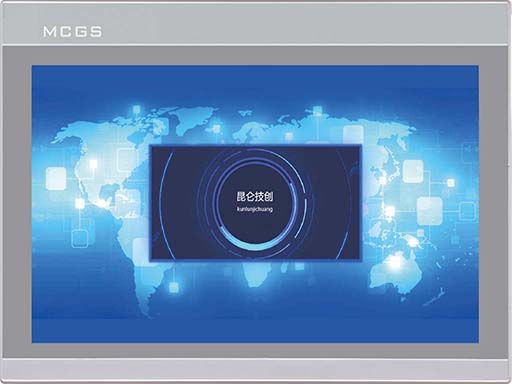
MCGS touch screen 485 communication precautions
1. Variables in the real-time runtime cannot simultaneously add channels and use functions to send data.2. In the parent device of the universal serial port, COM port indicates 232 or 485. In touch, C···
-
 202301-28
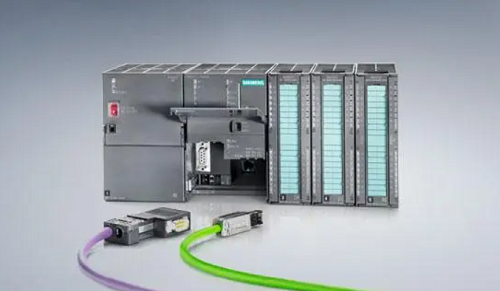
Siemens PLC controls Yamaha robots
This paper introduces the control strategy of Yamaha robot controlled by Siemens PLC, using the external IO port to set the command word, so that PLC can communicate with the robot, and instruct the r···


 +86 13811814778
 +86 13811814778
 Building 26, Liyuan Community, Chaoyang District, Beijing, China