
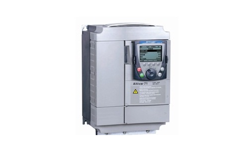
Schneider inverter commissioning procedure
Published:2023-02-23 15:29:24
1. Type recognition: Whether the type of frequency converter is common with the type of frequency converter purchased.
2. Transportation admission: After opening the package, check whether the frequency converter is damaged during transportation.
3. Voltage recognition: the field power supply voltage should be within the voltage range of the frequency converter. Otherwise, all the following steps stop.
4, step mechanical installation
5. Insulation measurement of motor and frequency converter: Then connect the frequency converter: connect the motor line to T1, T2 and T3 according to the drawing to ensure the connection and voltage are common; Connect the main power supply to R, S, T after ensuring that the power supply is closed: connect the control source: connect the speed of the given source. A connecting network with a network.
6. Power-on debugging and speech correction: speech selection will be displayed after power-on. (Only power on ** need to do this correction)
7. Restore factory Settings
8. Access level correction
9, set motor parameters: motor power, voltage, current, frequency, speed, and so on, and self-setting
10. Set acceleration and deceleration time: set a reasonable acceleration and deceleration time
11. Set maintenance parameters: thermal maintenance current value of the motor, current limiting value, etc.
12. Set the control source and frequency source: set the channel for starting the frequency converter in instruction 1.6, and the channel with the given frequency. Set ** high frequency, ** low frequency, etc.
13, the distribution of application function application function: such as braking logic control.
14. Confirm the steering of the motor: given the minimum frequency, point the inverter to recognize the steering of the motor; If contrary, parameter PHr in 1.4 can be corrected.
15. Record the current value of several frequency segments
-
 202212-29
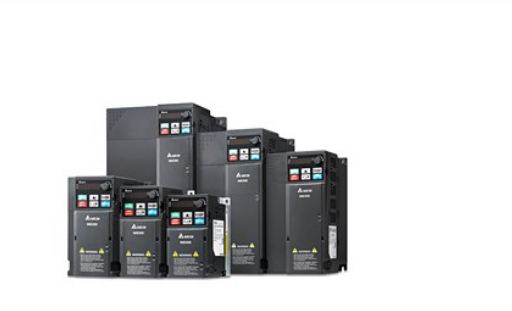
Delta frequency converter maintenance steps
First, the repair of frequency converter must first check whether the sound in the operation of the motor is abnormal, including whether it is sensational in the operation of the motor.Two, check whet···
-
 202301-17
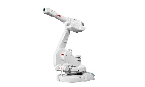
Installation and commissioning steps of ABB robot accessories
General steps for ABB robot installation and commissioning:1. Lift the robot body and control cabinet into place2. Cable connection between ABB robot body and control cabinet3. ABB robot teaching devi···
-
 202304-14
Delta inverter to reduce the failure rate method
Daily check Item 1 of Delta Frequency converter problem repair:Check whether the sound of the motor is abnormal during operation, including whether the motor is vibrating during operation.Daily view o···
-
 202212-29
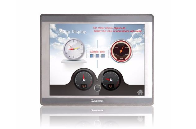
What symptom can WEINVIEW touch screen motherboard malfunction appear?
1. The motherboard cannot recognize/display peripheral devices.2. Peripherals will stop working for a few seconds or more.3. A slow startup may indicate that your motherboard is broken, although it co···
-
 202305-05
Delta inverter long-term idle points for attention
After the frequency converter is used for more than half a year, if the equipment is to be run again, the chance of damage may be greatly increased because of the placing environment, the service life···


 +86 13811814778
 +86 13811814778
 Building 26, Liyuan Community, Chaoyang District, Beijing, China