
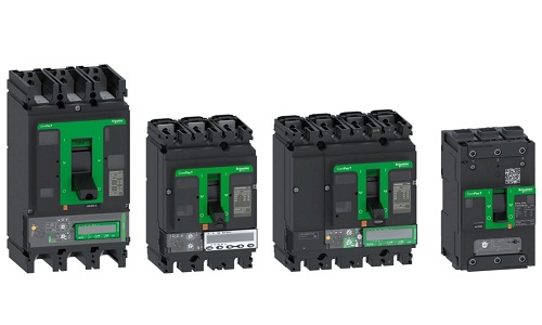
Schneider frequency converter disturbance and treatment method
Published:2023-01-29 16:23:57
A. Communication method:
(1) Radiation disturbance
(2) conduction disturbance
B. Disturbance rejection method
Nuisance signals transmitted by radiation methods are primarily weakened by wiring and by shielding the radioactive source and the nuisance line.
On the nuisance signal conveyed through the line, the primary method is to deal with the filter, reactor or magnetic ring installed on the input and output side of the converter.
Specific methods and precautions are as follows:
(1) Signal line and power line should be vertically crossed or slotted.
(2) Do not use different metal wires to connect with each other.
(3) The shield tube (layer) shall be reliably grounded, and ensure that the whole length of the continuous reliable grounding.
(4) twisted pair shielded cable should be used in signal circuit.
(5) The shielding layer connection address is far away from the converter as far as possible, and separated from the converter connection address.
(6) The magnetic ring can be used on the input power line and output line of the converter. The specific method is as follows: the input line is wound 4 times in the same direction, and the output line is wound 3 times in the same direction. When winding, please pay attention to the magnetic ring as close as possible to the frequency converter.
(7) Generally, shielding and other anti-disturbing methods can be adopted for disturbing equipment and instruments.
-
 202307-13
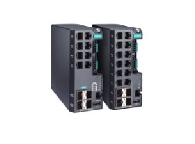
MOXA switch common faults and solutions
1. The physical layer is faultyPhysical layer faults refer to the hardware faults of the switch and the physical lines connecting to the switch.1. The hardware is faulty2. The physical cable is faulty···
-
 202302-08
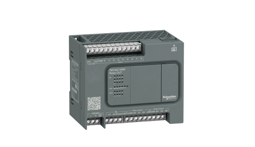
Schneider PLC control cabinet installation wiring method
(1) When placing signal cables with different properties into the same conduit, they must be isolated② Try to avoid multiple power lines contained in the same catheter. If necessary, a partition shal···
-
 202301-13
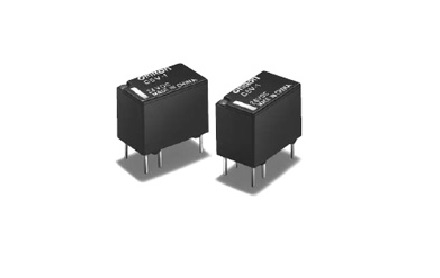
Working principle and application of Omron relay
Working principleWhen a certain voltage is added to both ends of the coil, a certain current will flow through the coil, resulting in electromagnetic effect. Under the action of electromagnetic force ···
-
 202301-16
TPC1262HI Common faults of MCGS on-state touch screen
TPC1262HI Common faults of MCGS touch screen(1) Black screen, flower screen and white screen(2) LCD screen aging, low high pressure, lamp aging(3) The LCD screen has no display, and the brightness is ···
-
 202302-15
How to calibrate the touch screen?
If the password of the system Settings of the Verantone touch screen hardware is lost, you can restore the factory Settings by system initialization. There are four ways to enter the Willenton touch s···


 +86 13811814778
 +86 13811814778
 Building 26, Liyuan Community, Chaoyang District, Beijing, China