
Mitsubishi PLC how to write hold circuit
Published:2023-02-02 14:44:56
Mitsubishi PLC has a very common circuit - a stick circuit. Persisting circuit means that when the external input switch is a button, it can adhere to the output by pressing the button through the persisting circuit, which is similar to the self-locking in the electrical diagram. We take Mitsubishi PLC as an example to write the persistence circuit.
First, we use X0 as the external input signal, and X0 is externally connected to the button. Click the mouse on the right side of the left bus bar of PLC software and enter "ld x0".
Two, adhere to the circuit needs to have a button to control its disconnection, we choose to use X1 to connect the external button to control its disconnection, in the PLC software with X1 normally closed contact X0, input "ldi x1".
3. Take Y0 as the output of PLC and input "OUT Y0" after the normally closed contact of X1.
Four, in the first step of the program, as long as the button is pressed, Y0 can be output, and the output will be disconnected when the button is released. The output of Y0 can be maintained only if the normally open contacts of Y0 are connected at both ends of the button. Enter "OR Y0"
5. If you do not use self-locking to control Y0, you can use setting and reset instructions to adhere to the output state, such as step 4 and 6. After writing the program press F4 to transform, and then press the test button to write the program to imitate PLC.
Six, click the test dialog box "menu start" - relay memory supervision.
7. In the monitoring dialog box, bring up the X and Y monitoring pages and click the Soft Component-Bit Soft component window. At this time, you can click X0 and X2, double click X0 twice is equivalent to the button function, then it is found that Y0 has persisted in output, press X1 again to release. Pressing X2 will make Y1 stick to output, and pressing X3 will reset Y1.

-
 202301-12
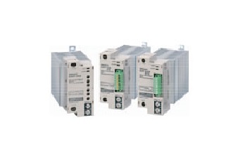
Delta PLC maintenance knowledge introduction
1. Delta PLC power-on running light is not on, ERROR flickers, the possible cause is: no program2. Delta PLC can not communicate with the computer, which may be: RS23 is bad3. If the power indicator o···
-
 202301-13
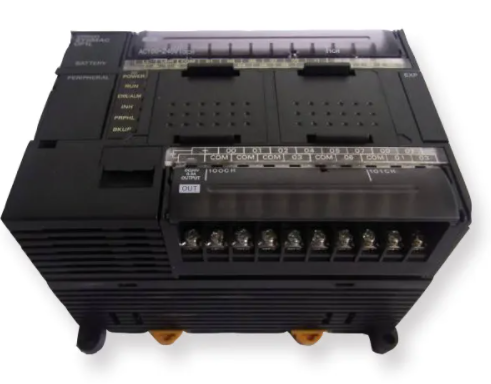
How to choose Omron relay
1, select the rated working current of electromagnetic relay coil: DC electromagnetic relay driven by transistor or integrated circuit, the rated working current of the coil (generally 2 times of the ···
-
 202302-28
Omron plc maintenance procedures and equipment regular cleaning regulations
I. Maintenance procedures, regular equipment testing and adjustment regulations(1) Check the connection of wiring terminals in the PLC cabinet every half a year or quarter. If loose places are found, ···
-
 202302-16
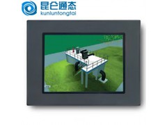
Solution of MCGS communication problem
1. How to check the communication status of the device in Kunlun Mode (MVGS)In all MCGS non-board devices (except some custom devices), *** channels are communication channels. That is, after entering···
-
 202212-29
Failure analysis of WEINVIEW touch screen can not be turned on
1. The power cable is incorrectly connectedThis may seem obvious, but make sure the power cord is connected to the back of the touch screen and plugged into a power outlet. If it looks connected corre···


 +86 13811814778
 +86 13811814778
 Building 26, Liyuan Community, Chaoyang District, Beijing, China