
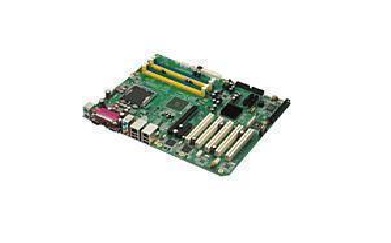
This section describes how to set the bios of Advantech mainboard
Published:2023-02-20 16:31:36
1. Set the system date and time
On the standard BIOS setting screen, press arrow keys to move the cursor to Date and Time, and then press Page Up/Page Down or +/&S722 to correct the date and time of the system.
2. IDE interface Settings
IDE interface setting is the number of IDE devices, type and operation mode Settings. The computer motherboard generally has two IDE interface slots, an IDE data line can connect to two IDE devices, so in the general computer can connect to 4 IDE devices. The meanings of each item in the IDE interface setup are as follows:
IDE Primary Master: Indicates the primary IDE interface for the IDE slot of the primary group.
IDE Primary Slave: indicates the secondary IDE interface of the IDE slot in the primary group.
IDE Secondary Master: indicates the primary IDE interface of the second IDE slot.
IDE Secondary Slave: indicates the secondary IDE interface of the second IDE slot. After selecting an IDE interface, you can click Page Up/Page Down or +/- to select the hard disk type: Manual, None, or Auto. Meanwhile, Manual states that the user is allowed to set the parameters of the IDE device. None indicates that the computer BIOS Settings are not detected when the machine is started. Generally, the most common use is to set the computer's list of action items. For example, if you want to install some software with the shut-off disk, you need to set the BIOS, set the BIOS list of action items to drive to start, so that the computer can enter the shut-off device software after restarting. Of course, also can in the computer BIOS, check the health of the computer, such as CPU temperature.
The device on the IDE interface, that is, the IDE device on the interface is masked. Auto indicates that the parameters of the IDE device are automatically detected. You are advised to use Auto so that the system can automatically search for hard disk information.
3. Configure the floppy Drive (Drive A/Drive B).
The Drive A and Drive B options are used to select the floppy drive type of the device. General motherboard BIOS support two floppy disk drives, in the system called A disk and B disk, corresponding to the BIOS Settings for Drive A and Drive B. If the floppy Drive is connected to the distorted end of the data cable, the BIOS should be set to Drive A. If there is no distorted orientation in the center of the connection, it should be set to Drive B in the BIOS. There are 4 options in the floppy Drive Settings: None, 1.2MB, 1.44MB and 2.88MB, now almost all use 1.44MB of 3.5IN floppy Drive, so according to the orientation of the floppy drive connection data line, set to "1.44MB, 3.5in" at the corresponding Drive A or Drive B. If the computer does not have A floppy Drive, set Drive A and Drive B to None.
4. Set Display Mode (Video/ Halt On)
The Video item is the display mode setting. The general system acquiesces that the display mode is EGA/VGA, which does not need to be corrected by the user. Halt On item is the system fault setting, mainly used to set the computer in the startup self-test fault, should take the corresponding operation.
5. Memory display
The Memory display section has three options: Base Memory(base Memory), Extended Memory(extended memory), and Total Memory(total memory). This parameter cannot be modified. Press Esc to return to the main screen of BIOS setting after completing CMOS setting.
-
 202512-25
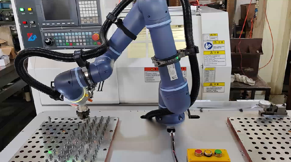
ESTUN Machine Tool Loading & Unloading Solution: Maximizing Throughput, Precision, and Agility
In the competitive world of industrial machining,the efficiency of material handling—specifically machine tool loading and unloading—directly dictates production cycles,product quality,and overall p···
-
 202308-03
Mitsubishi inverter commissioning procedure before use
First, Mitsubishi inverter no-load power test.1. Ground the ground terminal of the Mitsubishi frequency converter.2 Connect the power input terminal of the Mitsubishi inverter to the power supply thro···
-
 202302-15
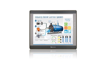
What symptom does WEINVIEW touch screen motherboard malfunction have?
1. The motherboard cannot recognize/display peripheral devices.2. Peripherals will stop working for a few seconds or more.3. A slow startup may indicate that your motherboard is broken, although it co···
-
 202302-10
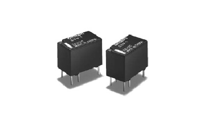
How to choose Omron relay
1, select the rated working current of electromagnetic relay coil: DC electromagnetic relay driven by transistor or integrated circuit, the rated working current of the coil (generally 2 times of the ···
-
 202301-17
Installation and commissioning steps of ABB robot accessories
General steps for ABB robot installation and commissioning:1. Lift the robot body and control cabinet into place2. Cable connection between ABB robot body and control cabinet3. ABB robot teaching devi···


 +8618621383628
 +8613811814778
 info@zhongpingtech.com
 Building 26, Liyuan Community, Chaoyang District, Beijing, China