
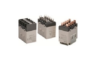
Parameter interpretation of Omron relay
Published:2023-02-10 15:55:43
Rated working voltage (current) :
Also known as coil voltage, it refers to the voltage or current that the relay can work reliably. When the relay is working, the input voltage or current of the relay coil should be equal to this value. In order to adapt to the requirements of different circuits, a certain type of relay has a variety of rated operating voltages or operating currents, such as DC24V, AC110V, etc.
Contact switching voltage and current:
The voltage and current that the relay is allowed to load. It determines the size of the voltage and current that the relay can control. It can not exceed this value when used, otherwise it is easy to damage the contact of the relay.
Contact load:
Refers to the current allowed through the contact of the relay and the voltage added, that is, the maximum load voltage that the contact can withstand. In use, in order to ensure that the contact is not damaged, can not use the small contact load relay to control the heavy load circuit.
Contact resistance:
In the closed state, there is a contact resistance between the coupling contacts, if the contact resistance is too large, it may lead to the controlled circuit voltage drop is too large or blocked; In the disconnected state, there is a certain insulation resistance between the contacts, if the insulation resistance is insufficient may lead to breakdown and discharge, resulting in the controlled circuit on; During the closing process, the contact bounces, which may damage the reliable closing of the contact. In the disconnection process may produce arc damage contact reliable disconnection.
Suction voltage (current) :
The minimum voltage at which a relay can produce a pull-in action is called the pull-in voltage. The minimum current value of the relay that can produce the pull action is called the pull current. In order to make the relay reliable, the actual voltage value must be added to the coil slightly greater than the rated voltage (current), but not too high, generally 1.5 times the rated value, otherwise it will burn the coil.
Suction time:
Refers to the time interval required by the contact from the release state to the draw state after energizing the relay coil.
Release voltage (current) :
The maximum voltage required to make the relay from the suction state to the release state is called the release voltage. The maximum current value required to make the relay from the draw state to the release state is called release current. In order to ensure reliable release of the relay as required, the voltage on its coil must be less than the release voltage (current) when the relay is released.
Release time:
Refers to the time interval required by the contact from the suction state to the release state after the relay coil is powered off.
Dielectric voltage resistance:
The value of voltage resistance between materials is selected in the process of making the relay.
-
 202301-06
Fault analysis and maintenance steps of WEINVIEW touch screen failure to turn on
1. The power cable is incorrectly connectedThis may seem obvious, but make sure the power cord is connected to the back of the touch screen and plugged into a power outlet. If it looks connected corre···
-
![[Gongboshi case] electric control cabinet box welding - Doctor of engineering independent brand to help customers intelligent upgrade production line](/static/upload/image/20221230/1672385439299376.png) 202212-30
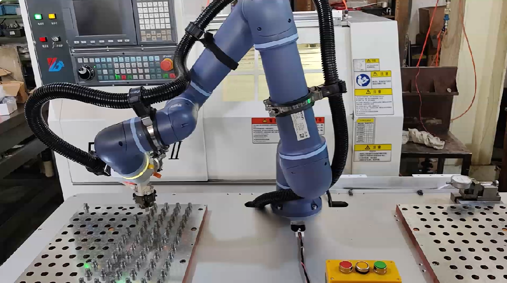
202212-30[Gongboshi case] electric control cabinet box welding - Doctor of engineering independent brand to help customers intelligent upgrade production line
Welding of electric control cabinet cabinetIn this case, the welding robot is combined with the Doctor of engineering robot positioner and gun cleaning station to realize the automatic welding of the ···
-
 202512-25
ESTUN Machine Tool Loading & Unloading Solution: Maximizing Throughput, Precision, and Agility
In the competitive world of industrial machining,the efficiency of material handling—specifically machine tool loading and unloading—directly dictates production cycles,product quality,and overall p···
-
 202303-24
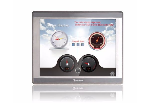
How does the WEINVIEW touch screen connect with the Omron NJ controller?
First, Omron NJ controller programming1. Create the structure data type required by the project. For example, the Boolean switch quantity used in this example is combined to establish a structure data···
-
 202301-16
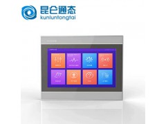
TPC1262HI Common faults of MCGS on-state touch screen
TPC1262HI Common faults of MCGS touch screen(1) Black screen, flower screen and white screen(2) LCD screen aging, low high pressure, lamp aging(3) The LCD screen has no display, and the brightness is ···


 +8618621383628
 +8613811814778
 info@zhongpingtech.com
 Building 26, Liyuan Community, Chaoyang District, Beijing, China