
Fault detection methods for Omron relays
Published:2023-04-21 16:02:21
Fault detection Method One
1. You can first check whether the voltage of the Omron relay is high or low. Generally, the maximum voltage is between 180V and 240V.
Fault detection Method two
2. In addition, when the Omron relay fails, the first thing to check is the external connection of the relay, to see whether the connection of the relay contacts is wrong or broken, falling off or other abnormal phenomena.
Fault detection Method three
3. Next, you can check the power supply circuit of Omron relay and use the meter to test whether the voltage of positive and negative power supplies is the same. If the voltage value measured is the same, it can be inferred that the relay is normal. If the voltage is not a problem, then the power amplifier delay and protection circuit can be carried out.
Fault detection Method four
4. At this time, the Omron relay also needs to measure the power amplifier's final circuit. You can visually check whether there are components burned. Need to be further measured, power amplifier tube emission stage resistance to the ground has DC voltage (normal value is within 0.7V) if there is DC voltage that is generally the power amplifier at the end of the circuit problem, then the treatment method can only replace a power amplifier tube emission stage resistance.
Omron relay note instructions
1. When installing Omron relay, it must not be pushed in too hard, so as not to damage shafting and code plate. The OMRON relay should be gently pushed into the bushing shaft.
2. When using the Omron relay, it is necessary to check whether the plate spring is loose relative to the Omron relay and whether the screw of the relay is loose, so as to avoid some faults and other accidents in the process of operation.
3. Do not randomly connect the terminal between the Omron relay to the wrong, otherwise it is easy to cause the damage of the Omron relay in power-on operation.

-
 202303-02
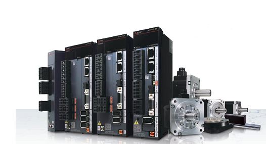
Mitsubishi servo motors one-button adjustment function
When different servo motors are installed on the machine for the first time, they will occasionally show a poor match with the machinery during operation, which will lead to vibration, noise and other···
-
 202302-17
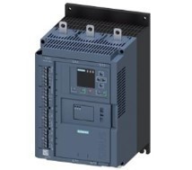
959698 reasons for failure of Siemens 3RW44 soft starter
3RW44 Soft starter 95,96,98 is a comprehensive fault, what causes it to operate?95,96,98 reasons for failure of Siemens 3RW44 soft starter95,96,98 is the normally open normally closed integrated fault···
-
 202302-15
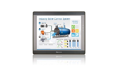
How to calibrate the touch screen?
If the password of the system Settings of the Verantone touch screen hardware is lost, you can restore the factory Settings by system initialization. There are four ways to enter the Willenton touch s···
-
 202303-17
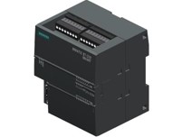
Installation guide for Siemens S7--200 equipment
The S7-200 can be mounted on a panel or standard guide rail. The S7-200 can be mounted horizontally or vertically.warningSIMATIC S7-200 PLC is an open controller. It requires the S7-200 to be installe···
-
 202302-15
What symptom does WEINVIEW touch screen motherboard malfunction have?
1. The motherboard cannot recognize/display peripheral devices.2. Peripherals will stop working for a few seconds or more.3. A slow startup may indicate that your motherboard is broken, although it co···

 +8618621383628
 +8613811814778
 info@zhongpingtech.com
 Building 26, Liyuan Community, Chaoyang District, Beijing, China