
Yaskawa servo drive debugging method steps
Published:2023-09-14 14:57:39
1. Basic wiring
The main power input is 220V, which is connected from L1 and L3 (the actual use should refer to the operation manual); Control power input r, t can also be directly connected - 220V; Motor wiring see page 22, 23 of the operation manual, encoder wiring see the operation manual, do not connect wrong.
Second, test steps
1.JOG test machine function Yaskawa servo can be tested only according to basic wiring; When the digital display is in the initial state 'r 0', press the 'SET' key, then press the 'MODE' key continuously until the digital display is' AF -- AcL ', then press the up and down keys to 'AF-JOG'; Press the 'SET' key to display 'JoG -' : press and hold the '^' key until 'rEAdy' is displayed; Hold down the '<' key until 'SrV-on' is displayed; Press and hold the '^' key to rotate the motor counterclockwise, press the 'V' motor to rotate clockwise, and its speed can be set by the parameter Pr57. Press 'SET' to end.
2. Yaskawa servo internal speed control mode COM+ (7-pin) is connected to +12 -- 24VDC,COM- (41-pin) is connected to the DC source; SRV -- ON (pin 29) connected with COM-; Parameter No.53 and No.05 should be set to 1: (Note that such parameters should be written into EEPROM after modification and re-powered) Adjust parameter No.53 to make the motor rotate. The parameter values are the rotational speed, with positive values for counter-clockwise rotation and negative values for clockwise rotation.
3. Yaskawa servo position control mode
COM+ (7-pin) is connected to +12 -- 24VDC, and COM- (41-pin) is connected to the DC power source; SRV -- ON (pin 29) is connected to COM-LUS1 (pin 3), SIGN1 (pin 5) is connected to the positive terminal of the pulse source (+5V); PLUS2 (pin 4) is connected to pulse signal, SIGN (pin 6) is connected to direction signal; Parameter No.02 is set to 0, No42 to 3, and No43 to 1. PLUS (4 pins) into the pulse signal, can make the motor rotation; Change SIGN2 to change the motor steering. In addition, adjusting parameters No.46 and No.4B can change the number of pulses required per revolution of the motor (that is, electronic gear).

-
 202301-05
Siemens F7453 after the treatment measures
1. Cause F7453 occursWhen Epos function is used, a bearing ring encoder will be set. If the numerical feedback of the bearing ring encoder presents problems, F7453 problems will be reported, represent···
-
 202302-27
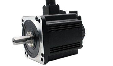
Delta servo motor how to choose?
In the selection of Delta servo motor, in principle should be based on the load conditions to choose. There are two kinds of loads on the motor shaft, namely damping torque and inertia load. The two l···
-
 202212-29
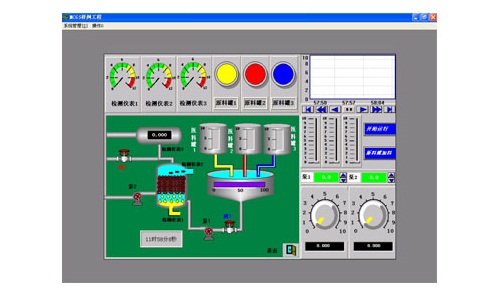
The composition of the configuration software of Kunlun MCGS embedded version
The user system generated by MCGS embedded version is composed of five parts: main control window, device window, user window, real-time database and operation strategy.1, the main control window: the···
-
 202410-16
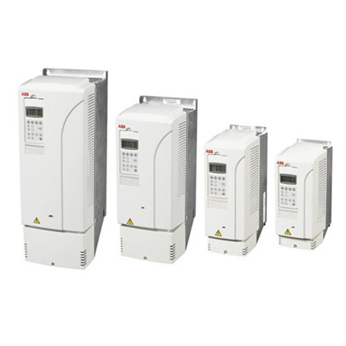
Enhance Efficiency with ABB Variable Frequency Drive
The key to enhancing plant performance lies in the variable frequency operation of ABB. You can rely on us.Main advantages of ABB variable frequency operation1.️ Energy efficiency reduces energy cost···
-
 202301-29
The role of Schneider instrument in air separation process
The surface of the instrument plays an important role in the air separation equipment and the process of gas purification. It is essential for the adjustment of the air separation process and the dete···


 +8618621383628
 +8613811814778
 info@zhongpingtech.com
 Building 26, Liyuan Community, Chaoyang District, Beijing, China